Liquid leaving 00420Kgs Inlet liquid flow rate comp. Liquid Distributor Design Calculation Liquid Distributor Design Calculation Bulan.
Column Internals Explained Part 2 Separation Technologies
Detailed information about the TUMWelChem Cell Model is presented in Hanusch et al.
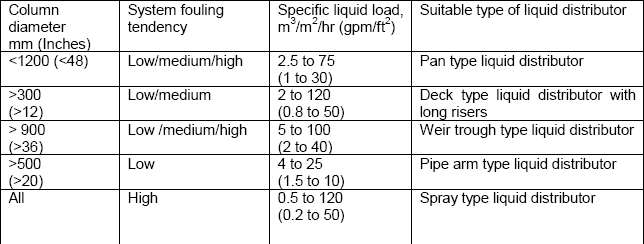
. D Q 040 100-A 060 B - 033 C - 75 1 A Cross section tower area not covered by point circles in. Distribution of the liquid onto the packed bed or structured packing is provided by appropriate liquid distributors. The main design criteria for any liquid distributor is to determine the number of drip points in relation to the column area irrigation density.
Place determine the selection and design of equipment. A typical liquid head level in a v-notch distributor is 13in 2575mm over the entire operating range while a more standard orifice distributor will maintain a head of 312in 75300mm. A crucial parameter in the design of a distributor is the liquid load uL required for the separation process.
In that manner first the minimum liquid head h min above a discharge hole of a liquid distributor must be determined. Liquid maldistribution is a major issue in the design of packed columns. In the case of heterogeneous flow the sparger has a negligible influence on the bubble size and gas-liquid mass transfer because the bubble dynamics are determined by the rate of coalescence and breakup which.
It is important to distribute the liquid flow equally across the column area in order to secure an intensive mass transfer between the phases. A distributor with a free overflow q 40 only saturates the line between the trough with water. An important design criteria is the number of drip points in.
A distributor with a side hole q80 and pipe guidance system creates the best distribution pattern where empty spaces are at a minimum. The number of TS theoretical stages required is calculated with a given liquid. Course Content INDEX Section Title Page 10 MATERIALS 3 11 DEFINITIONS 3 12 DUCTILE IRON PIPE 3 13 PLASTIC PRESSURE PIPE 6 14 PROTECTION 6 15 FITTINGS 7 16 VALVES 8 17 BOLTS NUTS and GASKETS 8 20 DESIGN 8.
It covers neither guidance on the selection of trays and packings nor some aspects of their performance characteristics. In a gravity head distributor this is the sum of the two components. In the same column operating at the same load but under a head of ho 3 mm the number required would be Z 80.
Note Number of side pipes adjusted to provide uniform entry per square foot of tower cross-section area. In determining the settling velocity in a liquid-liquid disper-. Liquid distribution in the packing is calculated in a top down sequence following a three-step distribution mechanism which considers the geometrical shape of the packing as well as the operating parameters liquid and gas load.
Thus if the liquid load is uL 1 m3m2h and the head is ho 1 mm the number of liquid outlets Z required per square metre of column cross-section would be Z 150 in a plate distributor with perforations of d 3 mm diameter. Liquid leaving the packing L inlet liquid flow rate Component removed 00207 00214 00420 KgSec. Distributor Grosir Murah Liquid Distributor Design Calculation.
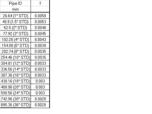
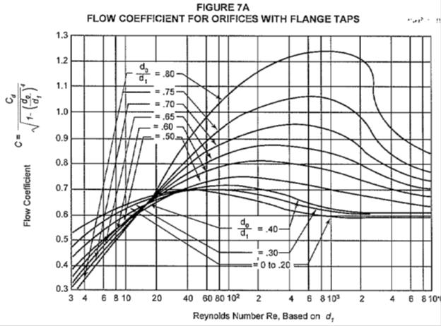
The dimensioning of liquid distributors In the dimensioning of liquid distributors not only the discharge coefficient but also other design determining criteria have to be taken into account. The design of liquid distributors and redistributors plays an important role in the performance of packed towers. 1 SCOPE This Guide deals with the design and rating of packed distillation columns.
Ceramic ACIDUR special stoneware metals C-steel stainless steels alloys and much more plastics PEPP PVC C-PVC PVDF PTFE and much more. Practical Design of Water Distribution Systems Jeffrey A. Removed 05 000497 Using 000497 as ordinate 1471 004 from graph Therefore G 004 05 16665 Tower cs area 01667 cs area mass flow rate G Tower diameter 04607m 4607mm 500mm Corresponding cs area 01963 m3s x 273 kmols x T in kelvin x 10 atm x 224.
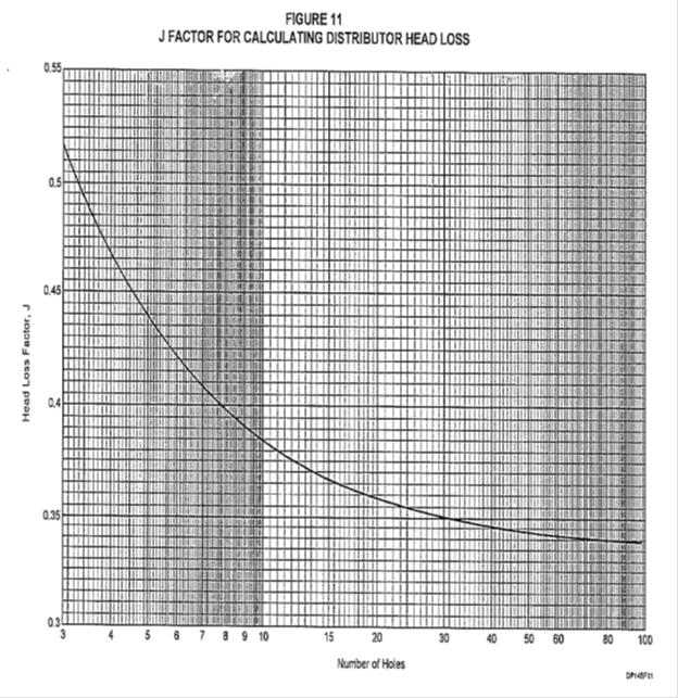
The driving force promot-ing coalescence is gravity and in a given system is proportional to r g r being the density difference between the two liq-uid phases. Typical design inlet liquid distributor using holes orifices on underside of distribution pipes. H O is the orifice head in.
This Guide has been prepared for GBH Enterprises. According to Bernoullis equation total head at a ny given point in liquid unde r motion is the sum of pressure velocity and elevation heads. Holes at wall should be spaced on same basis.
H OA h O h PD 1 where h OA is the total liquid head in the liquid distributor in. This paper analyzes liquid distribution in a 0634 m random packed column. Here the flow velocity of the.
VFF therefore offers a wide range of different designs and materials. Z g V h P 2 2 2 Where h total head feet P pressure head feet V velocity ftsec g gravitational acceleration 322 fts2. And h PD is the distributor head loss on the vapor side in.
Liquid distributors or redistributors should be selected according to the operating conditions and the type of packing used. Gas Distributor Design The effects of gas distributor design and its extent depend on the superficial gas velocity and fiow regime in which the BC operates. The diameter of the droplets is a critical parameter.
L G x ρg ρl05 0042002778 x 11846110005 000497 Use the 000497 as ordinate and pressure drop of 1471 NSqmm find the abscissa from the below graph. Advice on both of these is given in GBHE- PEG-MAS-610 - Selection of Internals for. A distributor with a base hole q60 generates a concentrated area below the trough.
2
1
Perforated Pipe Distributor Sizing Calculations Cheresources Com Community

Column Internals Explained Part 2 Separation Technologies
Perforated Pipe Distributor Sizing Calculations Cheresources Com Community

Importance Of Liquid Distributors Part 1 Mach Engineering
1
Perforated Pipe Distributor Sizing Calculations Cheresources Com Community
0 comments
Post a Comment